i. Design a composite beam with 150mm thick composite slabs with metal floor decking that would satisfied the above design criteria in bending
Question 1
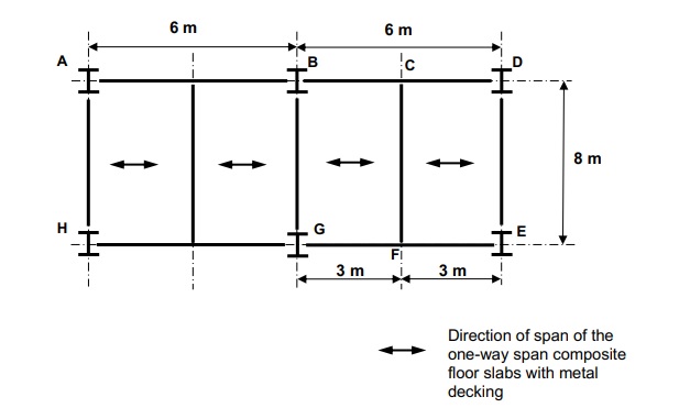
A typical floor plan of a multi-storey steel frame building is shown in Figure Q1. The composite floor slabs with metal decking are one-way spanning in the direction shown in Figure Q1. All joints are of simple connections.
The floor load consists of a characteristic permanent action of 4.0 kN/m2 and a characteristic variable action of 3.5 kN/m2. The weights of steel beams and concrete slabs are allowed for in the above permanent action. Beam CF shown in Figure Q1 is 8.0m long and can be assumed to be fully laterally restrained by the metal decking.
i. Design a composite beam with 150mm thick composite slabs with metal floor decking that would satisfied the above design criteria in bending
Given that: Diameter of headed shear stud, d = 19 mm Height of headed shear stud, hsc =120 mm Ultimate tensile strength of the headed stud, fu = 500 N/mm2 TATA Steel ComFlor 80 steel decking, thickness, t = 0.9 mm Concrete cylinder strength, fck = 35 N/mm2 , Ecm = 34000 MPa
ii. Check the composite beam for deflection. The deflection limit may be taken as ‘span of beam /360’. The deflection ‘d’ of a beam under uniformaly distributed load ‘w’ may be calculated from: where L = beam span, E = modulus of elasticity and I = second moment of area of the composite section

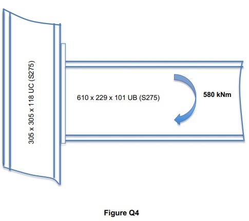
Question 4 For the rigid frame building’s connection as shown in Figure Q2, design an extended endplate BeamColumn moment connection using the ‘Abridged Plastic Distribution Method’ for manual design.
i) Column size: 305 ´ 305 ´ 118 UC (S275)
ii) Beam size: 610 ´ 229 ´ 101 UB (S275)
iii) Factored hogging moment of 580 kNm
Please provide a comprehensive design of the rigid joint with details that satisfied all the above criteria

100% Plagiarism Free & Custom Written,
tailored to your instructions