(a) Determine the vertical reactions at the supports.
1 For the loaded beam shown in Figure 1:
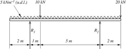
Figure 1
(a) Determine the vertical reactions at the supports.
(b) Sketch the shear force diagram for the beam.
(c) Calculate the bending moment at 1m intervals along the beam.
(d) Sketch the bending moment diagram for the beam.
(e) State the position and magnitude of the maximum bending moment in the beam.
2 For the I-section shown in Figure 2, calculate the values of the second moments of area about axis X-X and axis Y-Y. (Hint: work in centimetres).
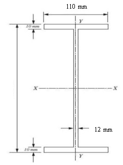
Figure 2
3 A beam of rectangular cross section 200 mm deep and 100 mm wide. If the beam is 3m long, simply supported at either end and carries point loads as shown in Figure 3.
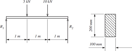
Figure 3
(a) Calculate the maximum bending moment.
(b) Calculate the maximum stress in the beam.
(c) At the point of maximum stress sketch a graph of the stress distribution through the thickness of the beam, indicating which are tensile and compressive stresses.
(d) Determine the dimensions of the cross section which will minimize the maximum stress value if:
- the cross sectional area of the beam can be increased by 20%;
- the beam section is to remain a solid rectangle;
- neither the breadth or depth of the beam section can be reduced below their original dimensions.
Show the dimensions of the proposed beam cross section with the aid of a sketch.
(e) Determine the percentage reduction of the maximum stress value when the new cross section is used
4 A column has the dimensions shown in Figure 4.
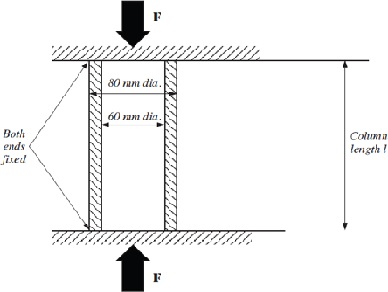
Figure 4
Column Material Properties
Young`s Modulus, E = 200 GN m–2
|
Yield stress, s = 140 MNm–2
(a) What is the minimum length of the column at which buckling is likely to occur?
(b) If the column is the length determined in (a):
(i) What will be the mode of failure?
(ii) At what load would you expect failure to occur?
(c) If the column is half the length determined in (a):
(i) What will be the mode of failure?
(ii) At what load would you expect failure to occur?
5 A horizontal force of 80 N acts on a mass of 6 kg resting on a horizontal surface, as shown in Figure 5. The mass is initially at rest and covers a distance of 5 m in 0.92 s under the action of the force. Assuming there are no energy losses due to air resistance and therefore that the acceleration is constant:
(a) Calculate the total energy expended in the acceleration.
(b) Plot a graph of the kinetic energy of the mass against time.
(c) Plot a graph of the kinetic energy of the mass against distance.
(d) Calculate the coefficient of friction between the mass and the surface
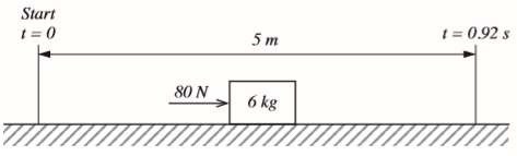
Figure 5
6 A mass of 0.5 kg is suspended from a flywheel as shown in Figure 6. If the mass is released from rest and falls a distance of 0.5 m in 1.5 s, calculate:
(a) The linear acceleration of the mass.
(b) The angular acceleration of the wheel.
(c) The tension in the rope.
(d) The frictional torque resisting motion.
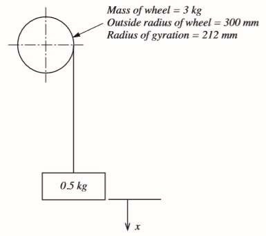
Figure 6
- END OF QUESTIONS -
1 A gear train is to be designed to transmit power from shaft 1 to shaft 2 with the following conditions:
(i) Shaft 1 (driven by an electric motor) rotates at 100 revs min–1.
(ii) Shaft 2 is to rotate at 400 revs min–1 in the opposite direction to shaft 1 against a load of 200 Nm.
(iii) The centre of shaft 1 is 300 mm from shaft 2.
(iv) The minimum number of teeth on any gear is 15. All gears must have a multiple of 5 teeth and have a module of 2 mm.
(v) The maximum number of gears permissible is 4 gears and the diameter of the largest gear must be minimized.
(vi) The centres of the gears should lie on a line which is as close to straight as possible.
(vii) All gear shafts have a frictional resistance of 5 Nm.
Carry out the following:
(a) Design a gear train which satisfies the above criteria. Use a sketch to illustrate your design, label the gears A, B, C, etc. from the driver to the driven gear and state the number of teeth on each gear.
(b) Determine the input power required at shaft 1.
(c) Specify the efficiency of the gear train as a percentage.
(d) Determine an equation for the efficiency of the gear train in terms of the load (torque) on shaft 2 with all other factors remaining constant.
2 There are two jack screw assemblies both with an ISO Metric Trapezoidal ‘Tr 16 x 3’ screw, one single-thread and the other double-thread. Each assembly raises and then lowers a load of 450 kg.
A ball-thrust bearing forms part of each assembly and therefore collar friction is negligible.
The coefficient of sliding friction for both screws is 0.08.
(a) For each assembly, determine:
(i) the pitch, pitch diameter, lead and lead angle;
(ii) the running torque required to lower the load;
(iii) whether they are back-driveable or self-locking?
(b) Which assembly is the most efficient in lifting?
(c) One way of ensuring that a lifting device can be made to self-lock is to use a thrust collar rather than a ball-thrust bearing. For any of the assemblies found to be back-driveable in (a)(iii), what is the minimum collar diameter required to ensure it/they would self-lock?
(Assume the same value of friction coefficient of 0.08 in all situations)
3 A mass of 0.3 kg is suspended from a spring of stiffness 200 Nm–1. The mass is displaced by 10 mm from its equilibrium position and released, as shown in Figure 1. For the resulting vibration, calculate:
(a) (i) the frequency of vibration;
(ii) the maximum velocity of the mass during the vibration;
(iii) the maximum acceleration of the mass during the vibration;
(iv) the mass required to produce double the maximum velocity calculated in (ii) using the same spring and initial deflection.
(b) Plot a graph of acceleration, a against displacement, x for a domain of
x = –10 mm to x = +10 mm
(4) The motion of a body along a straight line is simple harmonic. When 60 mm from the mid-point of the motion, the velocity of the body is 12 ms–1 and when 90 mm from the mid-point, its velocity is 4 ms-1. For the motion, calculate the:
(a) Amplitude
(b) Angular frequency
(c) Frequency
(d) Periodic time