Develop analytical and numerical mathematical models of fluid motion problems including boundary layer analysis and aerodynamic calculation
Question Brief
Workflow:
-
Review the literature
-
Undertake Boundary Layer analysis
-
Undertake Navier Stokes analysis
-
Undertake Two Phase Flow analysis
-
Undertake Aerodynamics analysis
-
Write a report
Plan a realistic schedule of work to complete this assignment on time and to a high standard.
Aim & Rationale
Aim
The aim of this assignment is to develop a proposal to analyse an oil and gas piping system. Why are we asking you to do this? The skills you demonstrate in this assessment are important because tis assessment focuses on a realworld engineering problem. For solving the problem, you need to find, evaluate, synthesis and use information from different sources and strengthen your critical thinking and report writing. These are critical factors to enhance the chance for your employability.
Task description
As a highly qualified Mechanical Engineering graduate you have been employed in the design team of a large multi-national company. The company produces a wide range of mechanical equipment for oil & gas industry. In their new project, a world-leading petroleum extraction company has asked for a new transport system for crude oil. This system transports oil from the production well to a nearby refinery. Before design and manufacturing the system, your company would like to understand the flow behaviour and to do so, they have hired you. The new transport system works as follows: the crude oil, after extraction, is guided on big horizontal plates so that the initial fluctuations due to high extraction pressure dampen. This dampening is essential before guiding the oil into big channels in which it is conveyed using moving plates. Due to space limitation, the transport system has a sharp 90-degree bending pipe after the channel. After this stage, gas (non-reactive with oil) is injected into crude oil for easier transportation via a circular pipe to the refinery. All the sections of the transport system are in the horizontal plane, so the effect of gravity can be neglected. Also, the temperature of the crude oil does not change significantly; therefore, the material properties of the oil remain constant. Measurements show that the oil density is 𝜌𝑜𝑖𝑙= 900 kg/m3 and its dynamic viscosity is 𝜇𝑜𝑖𝑙 = 1 kg/ms. Figure 1 shows a schematic of the transport system. Boundary layer analysis The first section (section ”a” in Figure 1) of the transport system is a flat plate with a length L = 20 m. At the beginning of the plate, as oil is just being extracted from the well and in contact with atmosphere, we can assume that its velocity is unaffected by air or any other solid object. Therefore, we can consider a uniform horizontal velocity for oil and measurement shows that it is 1 m/s. As soon as oil hits the plate, a boundary layer forms on the plate. Carry out boundary layer analysis on this plate (i.e. calculate the boundary layer thickness (δ), displacement thickness (δ*) and momentum thickness (𝜃)). For your calculations, list all assumptions you make. When possible, use excel to plot the boundary layer parameters as functions of the length from the beginning of the plate. Navier-Stokes analysis The oil is then guided (using a pump which is not shown in Figure 1) into a horizontal channel with rectangular cross section (section “b” in Figure 1). The height of the channel is H = 25 cm and its width is unit length (1 m). The pump helps the oil to move with a constant horizontal pressure gradient of 𝑑𝑝/𝑑𝑥 = – 0.05 kN/m3 inside the channel. Also, the channel is designed in such a way that its top wall (T) is fixed, and its bottom wall (B) moves at velocity UB= 10 cm/s. You can assume the oil flow as incompressible, fully developed, and steady.
-
Explain why you may assume the flow inside the channel is laminar? you can show this after your calculations in this section.
-
Considering all assumptions and also the flow as two-dimensional (you should justify later after your calculations), start from the full Navier-Stokes equations, simplify them and apply appropriate boundary conditionsto derive an expression for the velocity profile of the oil inside the channel. Determine the value and position of the maximum velocity. Plot the velocity profile as a function of the height from the bottom wall.
-
Derive an expression for the shear stress inside the channel and plot it as a function of height from the bottom wall. Calculate the shear stress, w, at the bottom and top walls.
-
Estimate the length of the channel that the pump can push the oil through it. Hint: the pump must cancel out the friction between the walls and the fluid, i.e., it should counterbalance the shear stress at the walls.
-
Calculate the oil volumetric flow rate and discuss on the accuracy of assuming a twodimensional flow. Hint: To get an estimation of the error in assuming a two-dimensional flow, you can calculate the flow rate in a rectangular channel with all wall fixed (you can assume UB=0 in your calculations) and compare this flow rate to available theoretical values. For a rectangular channel with all walls fixed, a half-height “a” (2a=H) and a half-width “b”, the theoretical volume flow rate can be calculated as:
𝑄𝑙 = 4𝑏𝑎 3 3𝜇 (− 𝑑𝑝 𝑑𝑥) [1 − 192𝑎 𝜋5𝑏 ∑ tanh ( 𝑖𝜋𝑏 2𝑎 ) 𝑖 5 ∞ 𝑖=1,3,5,… ]
where 𝜇 is the fluid dynamic viscosity and tanh is the hyperbolic tangent function. Plot a curve for the error as a function of the width (b) in the range 0.5𝑚 ≤ 𝑏 ≤ 10𝑚.
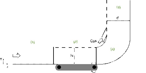
Aerodynamics analysis Oil leaves the channel and arrives at a quick 90-degree bending (bending c in Figure 1). The bending is not sharp, but the flow does not have enough time to follow its curvature. Discuss what would happen to the flow and using your knowledge of flow control methods, explain how could you control the possible phenomenon? What are the pros and cons of different flow control methods? Two phase flow analysis Oil will then flow into the horizontal pipe “section d in Figure 1” (diameter d = 30 cm) where it mixes with a non-reactive gas (𝜌𝑔𝑎𝑠= 8.0 kg/m3 , 𝜇𝑔𝑎𝑠 = 2e-5 kg/ms) with a volumetric flowrate Qgas= 180 l/s. The flowrate of the liquid, Ql, is what you calculated in previous sections (Navier-Stokes analysis).
-
Discuss which two-fluid model is more suitable to analyse the motion of oil & gas in this transport system and why.
-
Using the method you suggest in part (a), calculate the pressure drop in the flow from the point of gas injection to the refinery; the length of the pipeline is 8 km.
Extra Aerodynamics analysis
Roberto Carlos, a famous Brazilian football player, in a friendly match against France, scored a free-kick goal from a 35-meter distance with no direct line to the goal. He sent the ball flying wide of the players in the wall, but just before going out of bounds the ball hooked to the left and soared into the net. Using your knowledge of aerodynamics, explain how did he do this?
Report
Assessment will be by a written report, which should be well structured and well written with clear presentation. Requirements for Report Your report should be a detailed but succinct account of how you approached the problem and what you discovered. The report should be well written, professionally presented and well structured, detailing all the relevant aspects of your investigation. The report, including the main text and all the relevant figures, tables, references, appendix etc., must be 20 pages maximum. This page limit means that you should write concisely and restrict your attention to the key aspects of the study, while avoiding including figures, data or information, which are not necessary. If you write concisely then 20 pages should be plenty. You should demonstrate how you interpreted your results and discuss them in details. Your report is expected to have the following sections:
-
Introduction (including a literature review),
-
Aims and Objectives,
-
Methodology (details of relevant equations, etc)
-
Results,
-
Discussion,
-
Conclusion
-
Reference list.
It is recommended that you seek guidance and undertake background reading on technical report writing. You should avoid the following, which will result in failing to achieve high marks: Poor quality writing, structure and presentation Writing in the first person i.e. don’t use ‘I’ or ‘we’ Providing insufficient details of methods, so your work is not reproducible Inappropriate presentation of results i.e. showing the same results in a graph and table Graphs without axis labels and lacking/ incorrect units Failing to number and caption figures and tables and not citing them in the main body of text Failing to number equations and not citing them in the main body of text.
|
Learning outcomes |
|
Evidence |
|
Unit Learning Outcomes |
Develop analytical and numerical mathematical models of fluid motion problems including boundary layer analysis and aerodynamic calculation |
Report/ Presentation |
|
Evaluate different important flow types and features in practical fluid mechanics |
Report/ Presentation |
|
|
Appraise key aerodynamic issues and their interaction with other aerodynamics components and systems |
Report/ Presentation |
|
|
Assessment Criteria |
Apply skills of critical analysis to real world situations within a defined range of contexts. A critical awareness of current problems and/or new insights in Computer Aided Engineering and its applications. Ability to apply appropriate engineering analysis methods, supported by Computer Aided Engineering, to solve problems in engineering and to assess their limitations. |
|
|
Find, evaluate, synthesise and use information from a variety of sources. Awareness of how engineering activities supported by Computer Aided Engineering can promote sustainable development, based on the application of appropriate quantitative techniques. Advanced level knowledge and understanding of current Computer Aided Engineering tools and techniques. |
||